Saturday, February 27, 2021

Pipeline 1: Jetpack Jones - Adding Colours/ Restrictions

   To finish off the right completely, adding colour to the controls will allow them to show better in the view port and show the parenting chain. starting with the COG control, the  "enabling override" (in the attribute editor) is turned on and the main colour being used is a yellow shade. As everything is parented under the COG, all the controls turn yellow. 

  To sperate them, the override is turned on for all and colours are chosen depending on function. 

Colours added to Controls

  Following this, some restrictions are placed onto controls to stop overstretching. This was done using the minimum and maximum options in the controls attribute menu.  

Edit Attribute

  Some channels needs to be removed from the controls, this stops the rig being used wrong and breaking. Selecting the channel, it was made non-keyable and then locked/ hidden from the viewport. The scale channel is removed completely from all the controls as we have a overall world scale. 

Removed Channels - Pole Vectors

  For the Upper body, we add some restrictions. This is done in the "limit Information" section under the controls attributes, making sure the limits are checked on to take effect. These work by stopping movement beyond a certain point in 3D space. The arms needs to work within the limits of the post-space deformers.

Limit Information

 For the visibility, a new overriding control is placed. Using a star Nurb and placing it in the back arrow of the "World Control", it is then renamed as "Ctrls_Visibility" A Enum attribute is added called Ctrls (this makes a pull down menu) and the options created as On and Off. This control will work with a set driven control, placing the control as the driver and all the other controls placed in the driven. Setting a neutral key with all the controls visible as on, the off key is set with all the controls off and all the other channels are removed from the  new control. To finish the body rig, the visibility nurb is placed into the master group and coloured as grey.

Controls Visability

Wednesday, February 24, 2021

Pipeline 1: Jetpack Jones - Rigging the Upper Body

 Choosing a sphere nurb, rigging the clavicle is the first step for the upper body.  Placing the new nurb control to be just above the shoulder (using the mesh to help guide the sizing),it needed to easy enough to select but not too big.

  The control's pivot is then snapped onto the Clavicle joint, which is then duplicated, grouped and then placed in the negative axis. The joints are then constrained to the nurb using a parent connection, being renamed as L/R_Clav_CTRL.

  Using a new nurb circle and rotating 90 in Rotate Z,  it is then grouped (off_grp), parented to the shoulder and then repositioned correctly. This Nurb is then unparented,  duplicated twice and then reparented to the other joints in the arm (elbow and wrist). The new controls needed a little resizing and repositioning using the CV's (mainly the shoulder) before being connected in.

  With the controls all in place, parent constraints are used for the corresponding joints. 

  A hierarchy for the controls is needed to allow the correct movement when they are being utilized. The controls are parented as so and renamed for the left side:

 1. Wrist offset group - Elbow Control

2. Elbow offset grp - Shoulder Control 

 There is some errors involving the wrist joint when moving around the control, this is due to the  scripting on the forearm joint.  The script is changes to relate to the wrist control instead of the wrist joint : 

l_forearm_jnt.rotateX = L_Wrist_CTRL.rotateX*0.5

  For the fingers, a new taco nurb is placed above the wrist and repositioned/resized. This is then parented under the wrist control in the hierarchy. Following this, attributes was added to the hand control for each finger and the spread/ thumb twist. 

Left Arm Controls
Hand Attributes
  These controls are then duplicated, grouped and then placed in to the negative space. Once renamed as the Right controls, the hierarchy needs to be re-established and another small change made to the forearm joint scripting again. I had a little trouble connecting the right controls in to the hierarchy, this was due to forgetting to freeze the transformations after being flipped.  

Controls on Both Sides
 The connection editor was used to connect all the fingers and thumb joints to the controls on the left side first.

Connection Editor
  For the Spread channel, the Set Driven Key option was used. Placing the control as the Driver (Spread) and the base joints of the fingers (Rotate Y) into the Driven, a key awas established at 0 (neutral). The geometry helped  visually to place a key when the fingers are spread apart and clinched together. Once done, the animation editor is then made into linear for each piece of animation. I feel I made the together position a bit too far apart and could have been a bit closer.
  The process is then repeated for the right hand side.

  The shoulder groups are then placed in a hierarchy under the clavicle joints, which in turn is parented under the chest control.

 Selecting all the groups with controls in, these was placed into a new CTRL_grp and the scene cleaned up of anything that is not needed anymore. The rest in the outline is then placed into a Character_grp, which in turn is grouped under a new Master_grp.

  At this point, double translates are taking place when moving the mesh/controls around the scene. For creating the Master Control (renamed as "World_CTRL"), the 4 pointed arrow nurb was best.  Placing it under the character mesh and scaling up so it sits in the middle, it was then grouped together with the Master_grp. This new group is the named as "DO_NOT_TOUCH". This is to ward off anyone wanting to meddle with the rig.

  The World_CTRL and Master_grp is then parent and scale constrained together. To stop the double transformation when moving, we turn off the "inherit transforms" options for the geometry and misc. group.

  For the Ribbon spine, we place a scale constraint between the World_CTRL and the bind joints. This stops any strange deformation when scaling the character up or down.
Completed Rig so Far


Premise: Environment Explorations

  Taking a break from the creature designs, I decided to look at the environments/ dioramas. Although my project is aimed mainly at the creature design development/ rigging and movement, I wanted to give them a world to interact in. 

  Focusing at first on a bedroom, I played with the idea of it holding identity of someone who is quite imaginative and messy. This would help the creature fit in more as they would appear to have come from that person imagination, whilst allow plenty of places for them to hide. 

  I had thoughts around it being a child's room and these creatures being a part of their imagination. Therefore, they may leave "food" out for them and little titbits like that.

  Also, sketches conspired around using a laundry room where they would hunt for their food and interact.

  The pipes in the walls are aimed at the Tappers. Although the sounds (floorboard noises/creaks) they make are more like mimics rather then actual tapping/floorboard pressing, they would move around the house like how mice would due to their size and grouping. 

  There was some musing about using a real world projections (Photogrammetry) but that would mean being very careful with the camera movements. This technique can also cause problems with the characters sticking out too much if the texturing is too different to the world around them. With this is mind, I feel it may be best to chose a environment and model/texture it in the same style like the creatures.

  However, figuring out that style is causing a problem. I'm finding trying to capture the style of my influences quite a challenge, so it may be best to embrace my own style whilst using theirs to guide me in my designs instead. In talks with my tutor, the style in my project isn't so much visual, more in the answer to the questions being asked.

Bedroom Experiment 1
Bedroom Experiment 2
Pipe in the Walls

Laundry Room Sketch

Tuesday, February 23, 2021

Texturing Lesson Pt 4: Normal Maps, Tiff. Sequences and further Hypershade Nodes

Using Normal Maps 

  For this tutorial, we underwent the process of baking normal maps so that high res details can be placed on low res models. This technique is mainly used for games but is also good for keeping data usage low in animations scenes. 

  Exporting both the high res and low res barrels as .objs files, the data was imported into Xnormals to create a normal and occlusion maps. Moving into photoshop, a diffuse, specular and higher detailed normal map was rendered. 

  To create this higher detail normal map, once all the texturing was placed (making sure that the detailing was flat) a photoshop normal map rendition was taken. This newly textured version was then duplicated (one made as a blue only channel multiply layer and the other red/green overlay). The original was placed underneath these to create the final product.

  These maps was then plugged into a newly applied aiStandardSurface on the barrel, placing the normal map into the bump node channel and changing it to "tangent space". The normal map and specular is switched to a "Raw" colour data input and the ignore colour space turned on. The specular map required the "Alpha as Luminance" option to be set.

Normal Map
Specular Map
Diffuse Map
Final Outcome
Final Outcome


Tiff. Image Sequences Tutorial

    For this tutorial, we will be using set keys to create a continues Tiff sequences on a plane. Placing a new aiStandardSurface on the screen plane and import the images into the colour channel, switching in the "Use Image Sequence" option. 

   Although the image sequence works, we need to place set keys so the ball continues to scroll after the sequences finishes. Breaking the scripting in the "Image Number" box, we choose the "set key" option. This allows us to place keys at images 1 and 51, changing the pre/post infinity to cycle enables the sequence to keep playing once finished. Moving into the "Frame Extension" node, the "Tan" types are changed to linear to stop any slowing in and out. 

  To finish this, the tiff texture node was placed into the Emission channel from the Hypershade and the weight altered to make the images brighter.  

Original Set
Placing the "Set Key"
Changing the "Tan" types


Double Plane Tutorial

  I found this one to be a little more confusing, however I managed to do this by studying the originals Hypershade and its connections. 

  This was completed by inserting two texture nodes into a "Samplerinfo" node and a "Condition" node. These work by evacuating the condition of the scene in order to show the correct texture (the nodes asks the question of "is the .......... present?" and operating in a "True or False" scenario to show the textures set). 

Hypershade
Top of the Plane
Underside of the Plane

Monday, February 22, 2021

Pipeline 1: Jetpack Jones - Rigging the Spine

 Going back to the feet rigging, some re-scripting was needed to allow the ball twist to work in polar opposites when the channel boxes are being utilized. This meant breaking the current script in the right control and placing the following:

r_ball_twist_grp.rotateY = - R_Foot_CTRL.Ball_Twist;

This was done for all controls that operate in the rotate Y channel.

Pole Vectors and Scripting

  A arrow Nurb will be used for the pole vector controls. Reducing the scale, the arrow is firstly rotated 180 in Rotate Y and is then grouped twice (the first being called orient_off_grp and the second pos_off_grp). The position group is parented to the knee joint and removing the data in the channel box brings the control up to the knee. 

  Unparenting it, this allows us to bring the arrow outwards in the Z plane via the side view. In this new position, the controls world orientation is upside down. Rotating the control 180 in the rotate Z bring the orientation back the right way but the controls positioning is still wrong. To correct this further, we use the CV's to orientate into the correct position with some code in the MEL box; 

rotate -r 0 0 90; (entre in numeric pad)

We can now create the pole vector constraint

  With the first pole vector working, we duplicate the groups and control of the first control and bring it back to centre. Rotating the arrow 180 in rotate X, parenting to the knee makes sure the arrow is pointing in the correct direction. 

  Unparenting again, we snap the arrow to the same potion as the Left control and change the Rotate Z from 90 to -90 in the orient_off_grp. We can finish up connecting in the Pole Vectors constraints and rename the groups as L_ and R_. 

  For the hips, we use the double ended arrow Nurb. Lifting up the new control, it needs to be positioned just below the top of the hips whilst scaling down. The pivot is then snapped to the pelvis joint. Selecting the pelvis control and then the joint, we used a parent constraint with the off set on.

  To start on the spine, we need the Taco Nurb and snap it to the chest joint. When positioned, we rotate it slightly so as to fit with the chest and compress it slightly so as to not get in the way. This is then renamed as Chest_CNTL. 

  For the Spine, we need a few more controls. Using a circle Nurb from the control selection, we snap it to the central joint in the spine and shrink it down. This one is notated as Lumbar_CTRL.

  Removing the Geometry so to keep the viewport clear, some scripting needs to be removed to give better mesh movement. This means breaking the connections on the top and bottom ribbon spine joints, stopping any odd movements when moving the spine around.

For the Chest_CTRL, we need to create the following groups and move the pivots as so;

1. Group = chest_FW_SDK_grp = Pivot to Chest joint

2. Group = chest_SD_SDK_grp = Pivot to Chest joint

3. Group = chest_bend_SDK_grp = Pivot to Pelvis joint.

4. Group = chest_off_grp = Pivot to Chest joint.

 Then, selecting the control and then the chest joint, we can use a parent constraint to connect it all together.

  This is repeated for the Lumbar control but without the bend group. The finalised Lumbar-grp is then placed under the mid_aim_off_loc, then moving the mid_rbn_ctrl_joint under the  Lumbar_CTRL. This allows the lumbar control to move around with the ribbon spine.

  For the FK spine bend, we use a sphere nurb and snap it to the pelvis joint. Bringing it out, we re-size it  and remove any transformations, re-positing the pivot to the pelvis joint. This is renamed as Spine_Bend_FK_CTRL. (FK is just for a forward bend or forward kilometric). The forward bend is going to need some animation for it to work correctly.

  Using the Set Driven Key menu and setting the FK bend control as the driver, we bring in the chest bend SDK group in to the driven option. The rotate x is selected for both, keyed at zero and then position forward at 60, placing a key to finish. This is then repeated for the backwards bend at - 30 in the Rotate X. Once happy, we need to make the graph editor linear to stop any slowing in and out.

  This is repeated for the sideways SDK group but in Rotate Z and 50 each way. 

  For the spine FK, we need the spine to curve in a more natural way. Making sure the lumber pivots are placed on the ribbon spine centre joint, we bring in the FW groups for both the spine and lumbar into the driven.

  Using the rotate X on the driver, the driven needs to have translate and rotates X, Y and Z utilized and keyed in 0. Positioning the spine forward at 60, the chest FW SDK also needs to be placed at 60 and then both keyed. The lumbar control is then rotated slightly and brought backwards to allow a curve and and set. This is then repeated for the backwards bend but at -30, changing the graph editor to linear.

 The side bend is done the same way but is placed on the rotate Z in 60 each way.

  The twist in the spine needs to have some fall off. Using the groups for the side bends, we place keys at 30 in the Lumbar Rotate Y and 60 in the Chest. This is also done in the negative direction also.

  To finalise the spine, we need a COG control (centre of gravity). Using a pyramid Nurb, its rotated so the point is facing the spine and then resized. The pivot is placed on the pelvis joint and the control renamed as COG_CTRL. This control is mainly for constraints. Selecting the following Groups, we use a parent constraints so that they fall under the COG control when it's being moved;

- Pelvis Control

- chest_off_grp

- Spine_Bend_FK_CTRL

  This now completes the spine rigging.

Rig so Far

Premise: Tapper Sketches

  Following on from the Sock Stealer sketches, some progress has been made to the tapper. Originally, this creature would use the pipes an floor boards to annoy the Stealer so to grab scraps. however, I was finding it too hard to blend in the ability to be sneaky and to be heavy enough to make the noises required.  Looking at some animal calls, I decided that the Tapper will be able to mimic the sounds of the floor boards creaking an have something on their body to create a "tapping" noise. This means that I can concentrate on the stealth and climbing abilities more effectively, whilst utilizing a "group" behaviour. 

 These sketches are far from a finalised product, more will be made shortly.

Tapper Sketches


I have also starting experimenting with different bedroom environments so to be able to play with creature variation.

Thursday, February 18, 2021

Pipeline 1: Jetpack Jones - Rigging the Legs and Feet

   Before doing any rigging, a little clean up is required. In the outliner, we place all the Post-Space Deformers (Corrective Blend Shapes) into a group and call it PSD_Bshapes_Grp. The Skeleton will need to be placed into several groups. Selecting the ribbon spine locator group and the upper/lower body joints groups, these are placed into a new group and called skeleton_grp. The Misc group also needs to go into its own group, again being named as Misc_Grp. The geometry groups are to be grouped together and renamed as Geo_Grp. All the head objects (ears, Skullcap, etc) is in the skeleton group at present due to the parenting. 
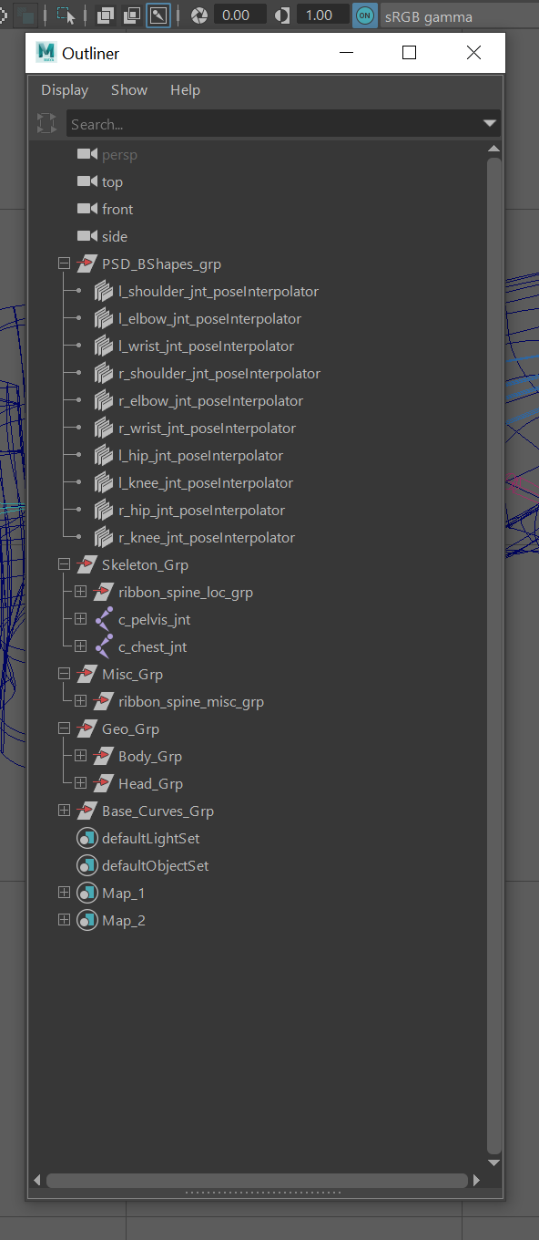
Clean Outliner

  After this, we remove the colour layers from the layer menu and then hide the Misc_grp so the locators don't obscure our view. With this done, we just check that everything is named correctly and all the allocated layers are working. 

  For the rigging controls, we import some specially created nurbs, making sure that "Merge selected name space" is on when importing them into the scene. This stop loads of long names being utilised in scenes. 
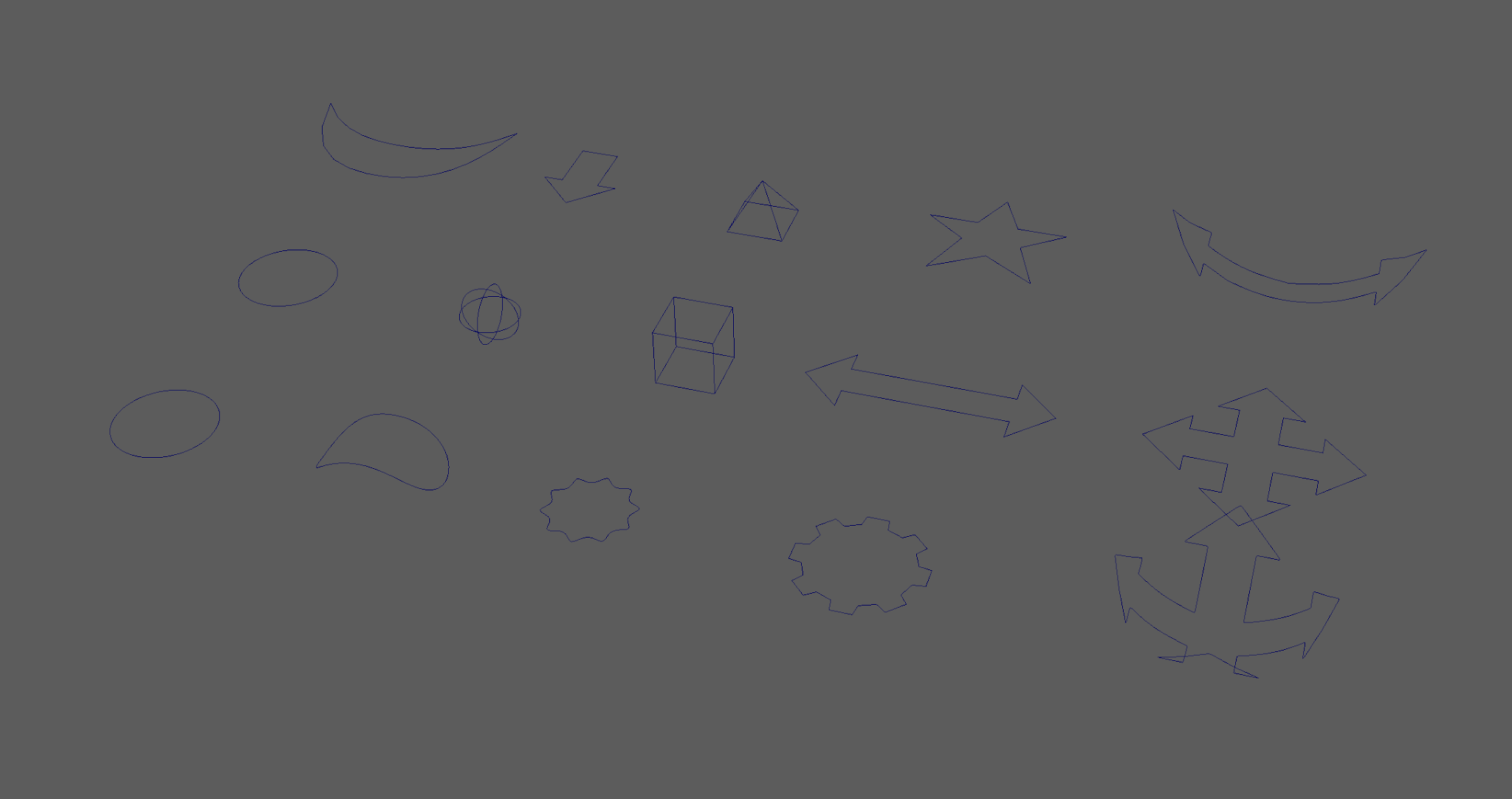
Nurb Controls
  For the IK handles, the rigging will revolve around the solver properties and the sticky options. As we have a 3-chain structure in the leg, we need to use the Rotate-Plane solver with the Sticky on (Sticky remembers where the IK is situated so we can compress the leg downwards correctly and allows a weighted effect). 

  However, using a 3 chain causes a "broken" shin effect. This is fixed by moving the "effector". Making sure "sticky" is turned off and creating a IK from the hip to the shin joint, we can select the "effector" in the outliner and "insert" move it to the ankle. To get the correct movement for the IK, turning on "sticky" via the  Solver Attributes will make it work.

For single chain joints, we can us the "Single-Chain Solvers".

  Removing the geometry from the viewport, we use the above technique to create the left_Leg_IK. Once the Sticky is placed, single chins are made from the ankle to the football and then to the toe. The Ankle IK is call L_stabalizer_IK. This is then repeated for the right leg and renamed as R_. 
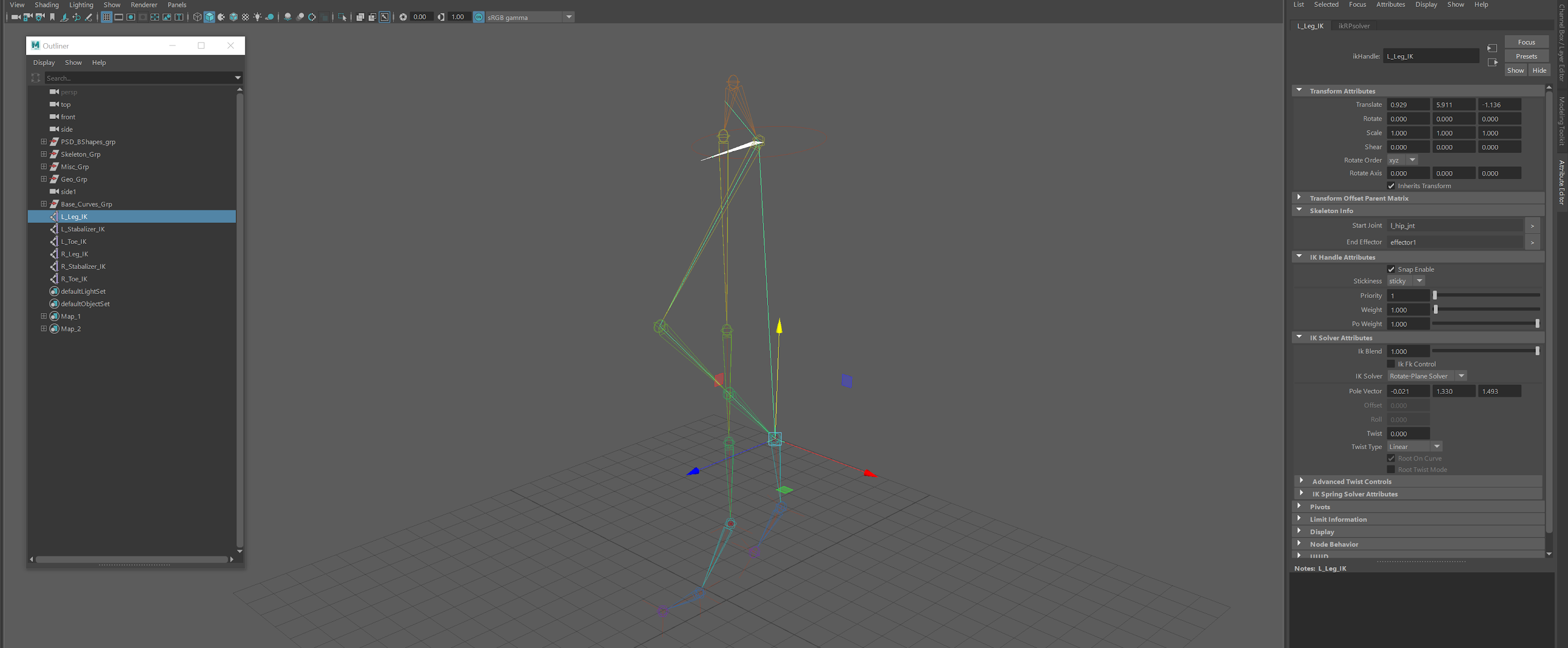
Leg IK's
The IK handles will look "flipped" when created, this is due to the joints on the right side being mirrored and having opposite orientations. 

  Creating a locator and reducing the size to 0.5 in the local scale, we place it onto a layer with a yellow colour to help it stand out in the viewport. This first locator is snapped to the foot ball and then duplicated, positioning it to the front of the foot (using the geometry as a guide). Its best to use snapping to make sure the locators are in the correct place. A third is then placed at the back of the foot and two more positioned on each side (one left and one right). These need to be placed in alignment with each other and in a central position of the foot. Placing all these locators in a group, the pivot need to stay where it is for easy flipping to the right side. 
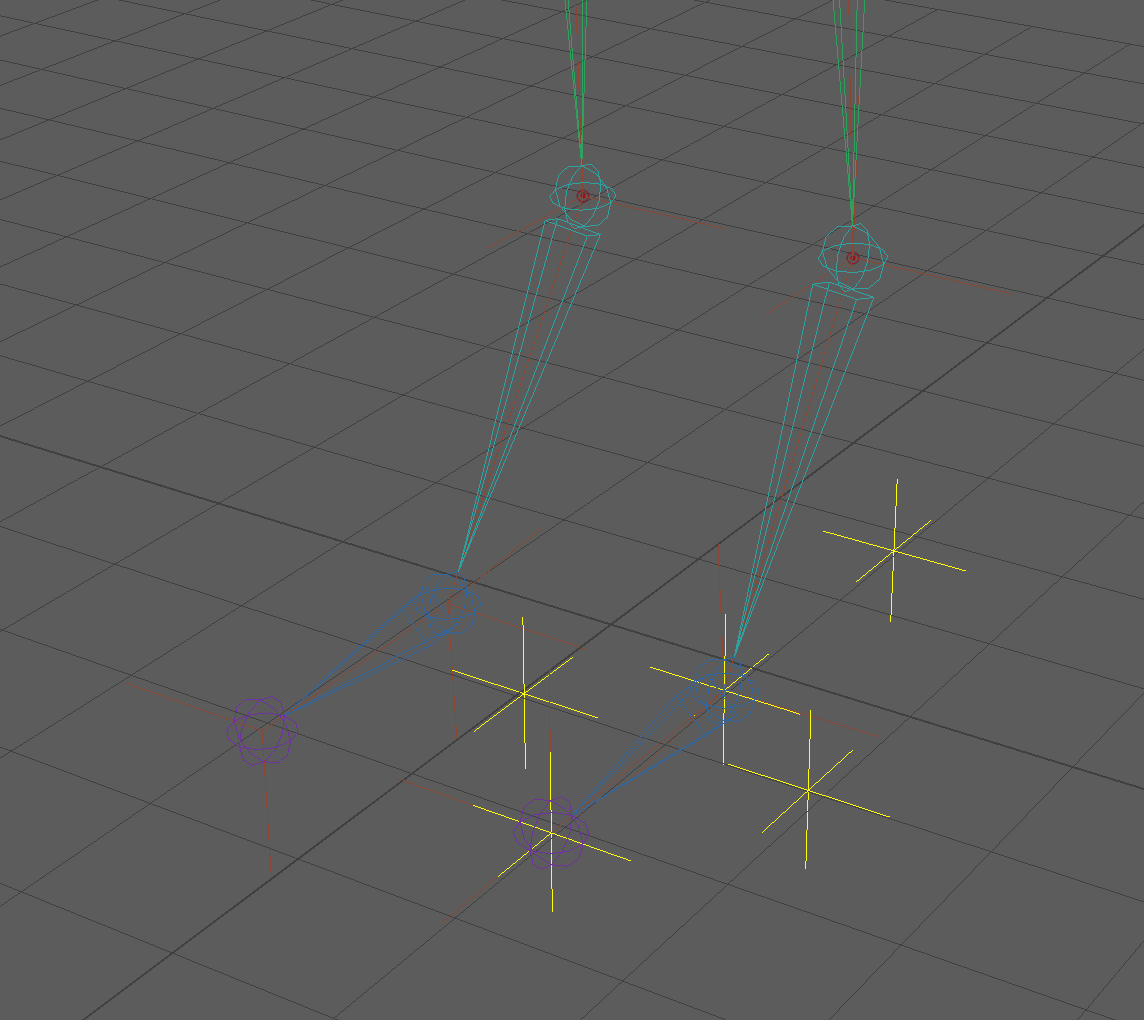
Locators

  Turning off the geometry again, we start placing the left IK's into groups and move the pivots to the following positions: 

 1. Leg_IK = Group = move pivot to the football joint = named l_heel_lift_grp.

 2. toe_IK = Group = Pivot to football joint = named  l_toe_tap_grp.

3. Select both new groups then the Stabalizer_IK = Group = Pivot to the back locator = named l_foot_tap_grp

(placing a Stabalizer stops the foot disappearing below the ground when being utilised)

4. l_toe_tap_grp = group = Pivot moved to front locator = named l_pirouette_grp.

5. l_pirouette_grp. = Group = Pivot to football locator = named l_ball_twist_grp.

6. l_ball_twist_grp = 2 Groups = 1st group called l_sd_ft_roll_l_grp, 2nd group called l_sd_ft_roll_r_grp = Piviots moved the the left and right sides according to group names. 

(These will have Set Driven Keys on later so SDK needs to be present in name).

7 .l_sd_ft_roll_r_grp = group = pivot moved to ankle = called l_leg_grp

8.  Go back to l_heel_lift_grp, copy name, group, move pivot back and rename as l_heel_lift_SDK_grp

9. This is then repeated for the toe tap, foot tap and the pirouette groups.

The locators are then flipped and the grouping repeated for the other leg but using r_. 
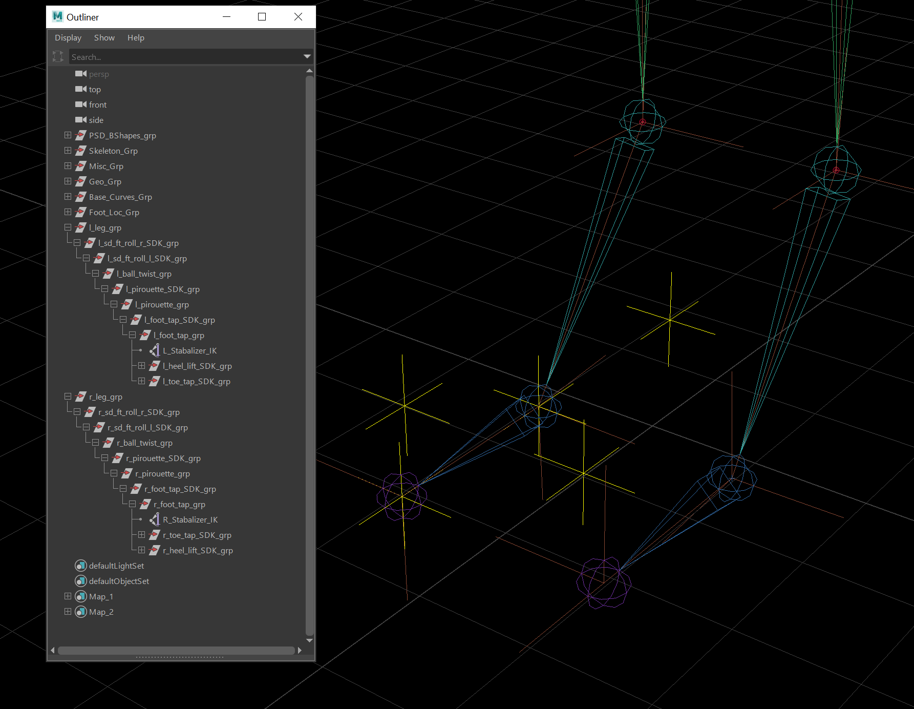
IK Grouping
  Selecting the circle nurb with 10 CV's, we duplicate it and ungroup it/ remove it from it's layer. Placing it around the left foot, we use the CV's to sculpt a effective control shape with a slight lift at the back. When happy with the shape, we freeze the transformations and deleted history to remove any problems. This is then renamed as L_Foot_CTRL.

  Using the Add Attribute option, we place some new channel boxes. We need to make sure they are added as "floating" channels.


  Moving the pivot for the control to the ankle, some changes are going to be needed for the shin joint scripting. Copying the leg group expression in the expression editor (l_leg_grp.rotateY), we replace ankle joint code with the group one. This is repeated for the right side too. 
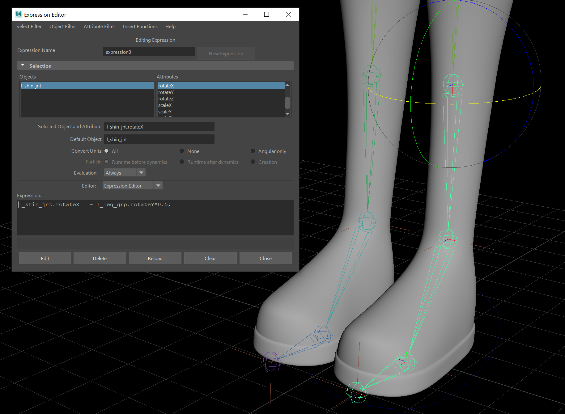
Expression Change
  Working to connect in the control, we select the control, the l_leg_group and create a parent constraint. Taking note of positive and negative directions when moving the joints, we use the connection editor to load the control the left side and the group wanted into the right, connection up as so; 

1. Heel_Lift = rotateX (pos only)
2.  Ball_Twist = rotateY 
3.  Pirouette_U_D = rotateX
4.  Pirouette_L_R = rotateY

  The foot tap and toe tap is going to use coding to connect. Selecting the control and then the rotateX channel, we go to expressions and copy the code. Moving into the toe tap group (not SDK) rotateX channel, we bring it down to the expression box and place the copied code after. As it need to be in reverse so to move in a positive direction, we place a minus before the left foot control code. This is then repeated for the foot tap channel.


 For the Foot Rolls, this is created using Set Driven Keys. Selecting the control and going to the Set Driven Keep menu (under animation), we load in the driver as the control and the SDK groups in the driven. Selecting the Rotate Z ( and making sure everything is at 0), we press key to give us a starting position. 

Changing the side roll channel to +30, we rotate the left roll SDK group to -30 and key. This is then repeated to the other side but placing -30 in the channel and -30 on the right roll SDK group.

  Going into the animation editor, we change the spline to linear so stop any fall off. 


  For a foot roll forwards, we bring in the other groups into the driven (pirouette SDK, foot tap SDK, heel lift SDK and toe tap SDK), select FW foot roll channel on the control (Driver) and make sure everything is at 0 before pressing key. We then place -30 in the FW Foot Roll channel and then rotate X  -30 into the foot tap and toe tap groups, pressing key to animate. Going back to 0, +30 is placed into the FW foot roll channel and +30 in the heel lift SDK rotate x channel, pressing key again. 

 Going back to 0 one more time, we place +60 in the FW foot roll channel and bring the pirouette SDK group to +40 in rotate X, finalising with key.

  With the SDK's all set, we go back into the graph editor to set all the SDK group to linear. 

  For the twist in the IK, the connection editor is used and match up the Twist channel to the twist movement.

 The foot control is then duplicated, group and  flipped so be on the right hand side. We need to make sure the history and transformations are again removed, the connection hierarchy is then repeated.


  To finish off the legs, pole vectors will be needed to stop the knee popping. 

Premise: Sketches Development Pt 2

  Using the previous designs, I started to concentrated on one and tried to push it further. Although it still needs work to catch a grumpy/territorial appeal and to show the correct movement, It feels like it's starting to get somewhere. Next I will work on the other two creatures and some environment sketches.  
Sock Stealer Development Sketches

Wednesday, February 17, 2021

Premise: Sketches Development Pt 1

  Continuing on with making sketches for the Sock Stealer, I've tried added some colours. These need a lot of work, they are far to complicated (straying too far from the inspiring artist: Goro Fujita) and I need to think deeper about small quirks and how it would adapts to it's environment. I tried to look at children's drawing and toys for inspirations in proportions. 

Nature: Territorial, greedy (food orientated), grumpy and easily distracted.
Changes colours to blend in and makes itself larger to intimate trespassers.
Animals: Frogs, Pigs, Lizards and bulldogs.

Sock Stealer Developing Sketches


Tuesday, February 16, 2021

Texturing Lesson Pt 3: Adding Decay and the Hypershade

  Working with last lessons progress, we started by adding some decay to the book cover and pages with concrete textures. These was made up as bump, specular and diffuse maps. Next was to work with layering in the Hyper Shade using the aiLayerRgba and aiShadingLayer nodes, the following textures was placed along with some ramp lighting to bring us the final outcome so far. 

  I tried to make the grubbiness of the book interesting but not too beat up, further details and decay will be done via substance painter. 

Original Progression
Concrete Map
Added Dirt via Concrete
Decal/ Embossed Mask
Bumped Embossed Detail
Progress So Far
Hypershade

Major - Submission Post: Final Animation, Reflective Statement and Links

Final Reflective Statement When starting the Major Project, there was still quite a lot of work left over from Minor for the planned final...