Today we have started learning the rigging process, the rig is essentially the skeleton of our models. This rig is completely made form scratch so to help us understand the creation process, and how to apply controls.
When creating the joints, the most important element to the is the rotation. This means that all the values should be at 0 though so to stop malfunctions. In creating our first joint, we counted 11 spaces up from the grid, pressing X to keep the values clean and clicking to create. From here we went 5 spaces down and one offset forward to create the knee joint, then proceeded to make the ankle 1 up from the grid. Following this, 2 more joints was made on the grid line. The offset was 1 forward form the ankle for the ball joint and another for the toes.
The bones between the joints show the direction of hierarchy and the flow the structures movement. Selecting the firstly made joint (Hip) will select all the joints in the hierarchy downwards. Now the joint are created, getting the names on them is important so we know which is which. For joints, we place the JNT short hand at the end.
As the leg we made is central of the grid, we have to move the leg out to a side for perspective of the character. This one was moved out to the left. We then make Inverse Kilomatics, these make the joints move more realistically. Legs can have 2 rigs to help in movement.
The pelvis has the shorthand of C (this is for central), in making the hip we created a joint just above the leg. We then use the parent contain, selecting the hip first (child), then the pelvis (parent) and pressed P. This then creates the hip bones (Parenting constrains face in the parent to child direction, but the child must be selected first when creating).
Following this, we used the mirror joint to make the right leg. Entering the mirror joint options, we changed the mirror access to XY and the type search from L_ to be replaced with R_, this automatically changes the name to the shorthand desired for the right leg.
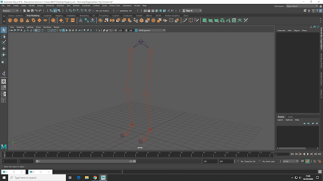 |
| Mirrored Leg |
For the legs we need 3 Inverse Killomatic Handles. The knee will be a rotation IK and the other 2 a straight chain. Open the options menu on the IK handles (under the skeleton menu), we needed to have Sticky selected on and the Rotate Plane Solved showing. Holding X, we firstly selected the hip joint, then the ankle, making the control appears. Once done and renamed L_Leg_IK, we do the same for the right leg. Its important for the knee joint to be slightly off set and not in a straight line with the hip and ankle joints, this allows the flexibility needed in the knee.
For the rest of the foot joints, back in the IK handles options we turn off sticky and change to single chain solvers. Then again holding X, click on the ankle, ball and toe joints, creating out next control. The ball joint IK is renamed as Stabilizer, so not to get confused.
 |
| Added Inverse Killomatics |
Now all the IK handles are set and the joints rigged, pole vectors in the knees stops over stretching and popping. Pole vectors also help in the knees left and right movement. With the pole vectors selected, we create a arrow in the space around the legs, then resize and placing it before the knee. Using the IK handles on the knees and the arrow pole vector, we then join them using the pole vector control under the constrain menu.
Its important to freeze transformations and delete history after making controls and once set in the right place. Leaving unneeded history will break the rig.
Following the creation of the pole vectors, we move the Left Leg IK pivot point to the ball joint. This helps with the heel and foot lifting movement. The pivots are moved using the move tool, pressing D and then holding V to move the pivot though vertices. We then created a NURB circle and resize it to make a left foot shape, and another around the hip joint.
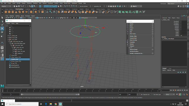 |
| Hip Joint and Foot NURBS |
The foot and knee NURB controls was then duplicated, grouped and placed in Scale X -1 so to be placed in front of the right leg knee and under the right foot (rename accordingly). The hips was constrained using the point and orient controls, allowing the hips to tilt and twist naturally (point is for translation movements and orient for rotation). Under the controls, we made sure that maintain offset is checked, and then applied the control. When joined together, the channel box attributes lights up blue to show they are linked. Clicking on the NURB control then moves the hips, rather the using the individual joints.
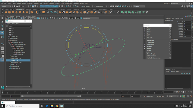 |
| Hips constrained with NURBS |
The Foot Group has had added attributes such as heel tap, foot roll and toe tap etc. So, connecting the foot is a lot more complicated, and the connection editor is best here. Selecting the NURB control for the desired leg, we click on the Foot group wanted for the connection. Under this, we then make our way though the foot group and connect what we want to the NURB control (all of the attributes needed to use Rotate X, apart from Pirouette_L_R which needs Rotate Y) Once the connection are formed, they highlight yellow in the attributes box and become italic in the editor.
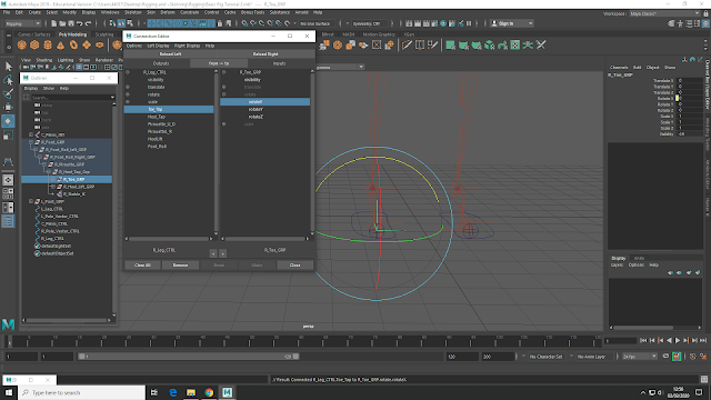 |
| Added Connection using the Connection Editor |
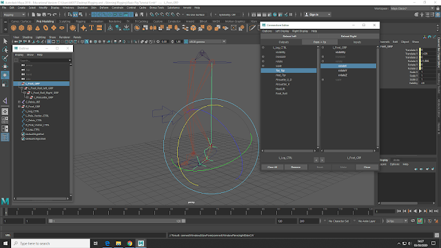 |
| Connection Editor |
Next its moving onto the foot roll control, and the creation of the spine. For Rigging, its best to work from the feet upwards, this is because the legs are the most complicated to make.


No comments:
Post a Comment
Note: Only a member of this blog may post a comment.